An ammeter should be connected in the circuit in series with the resistors. To measure the potential difference across the resistor it should be connected in parallel, as shown in the following figure.
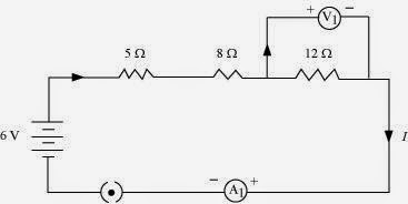
The resistances are connected in series.
Ohm’s law can be used to obtain the readings of ammeter and voltmeter. According to Ohm’s law,
V = IR,
Where,
Potential difference, V = 6 V
Current flowing through the circuit/resistors = I
Resistance of the circuit, R = 5 + 8 + 12 = 25Ω
I = V/R = 6/25 = 0.24 A
Potential difference across 12 Ω resistor = V1
Current flowing through the 12 Ω resistor, I = 0.24 A
Therefore, using Ohm’s law, we obtain
V1 = IR = 0.24 x 12 = 2.88 V
Therefore, the reading of the ammeter will be 0.24 A.
The reading of the voltmeter will be 2.88 V.